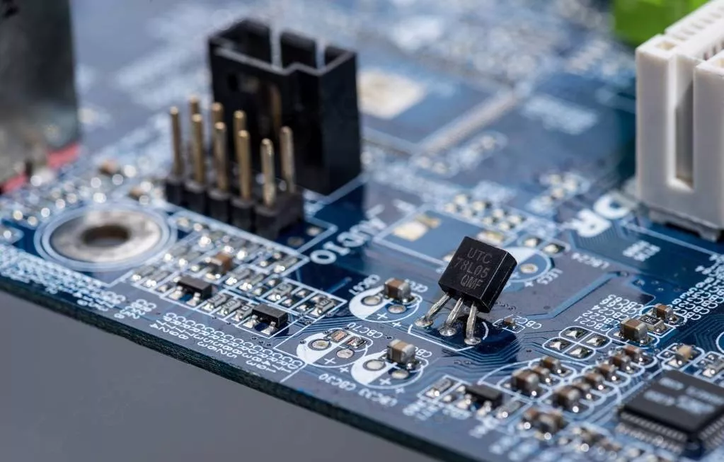
Remedy for BGA Pad Peeling Off
The full name of BGA is Ball Grid Array (Solder Ball Array Package), which is to make an array of solder balls on the bottom of the package substrate as the I/O end of the circuit to interconnect with the printed circuit board (PCB). The device packaged with this technology is a surface mount device.
BGA packaging appeared in the early 1990s and has now developed into a mature high-density packaging technology. Among all packaging types of semiconductor ICs, BGA packaging has the fastest growth rate during the five-year period from 1996 to 2001. In 1999, the output of BGA was about 1 billion. However, so far, this technology is limited to the packaging of high-density, high-performance devices, and the technology is still developing in the direction of fine pitch and high I/O terminal count. BGA packaging technology is mainly applicable to the packaging of devices such as PC chipsets, microprocessors/controllers, ASICs, gate arrays, memories, DSPs, PDAs, and PLDs.
The main process of BGA
1. Flatten the front plug hole: it is suitable for single side exposure or partial exposure of the solder mask at the BGA plug hole. If the diameter of the two plug holes differs by 1.5mm, this process is used regardless of whether the solder mask is covered on both sides;
2. Solder resistance plug hole: applied to the board covered by solder mask on both sides of the BGA plug hole;
3. Plug holes before and after leveling: used for thick copper foil boards or other boards with special needs. There are 7 kinds of plug hole sizes: 0.25, 0.30, 0.35, 0.40, 0.45, 0.50, 0.55mm.

The Remedy for BGA pad Peeling off
1. Clean the area to be repaired.
2. Remove the failed pad and a small piece of wire.
3. Use a knife to scrape off residual glue, stains or burned materials.
4. Scrape off the solder mask or coating on the connection.
5. Clean the area.
6. Dip a small amount of liquid flux on the connection area of the board, apply tin and clean it. The overlap length of the solder connection should be less than twice the wire width. Then, the connection of the new BGA pad can be inserted into the via hole of the original BGA pad. Remove the solder mask of the via hole and treat it appropriately, and the new pad area on the board surface must be smooth. If there are exposed inner board fibers or deep scratches on the surface, they should be repaired first. The height of the replaced BGA pad is critical, especially for eutectic solder ball components. Remove the solder mask material between the BGA pad and the board connection or via hole to maintain a low profile. If necessary, lightly grind into the board surface to ensure that the height of the connection does not affect the replaced components.
7. Choose a BGA replacement pad that is closest to the pad to be replaced. If you need a special size or shape, you can customize it. These new BGA pads are made of copper foil. The top surface of the copper foil is tin-plated and the bottom surface has adhesive bonding pads.
8. Before trimming the new pad, carefully scrape off the adhesive bonding sheet in the solder joint connection area on the back of the new pad. Scrape the resin substrate only from the solder joint connection area. This will allow welding of exposed areas. When handling replacement pads, avoid fingers or other materials contacting the resin substrate, which may contaminate the surface and reduce the bond strength.
9. Cut and trim the new pad. It can be cut from the tinned side, and the length of the cut should ensure the maximum allowable welding connection overlap.
10. Put a piece of high temperature tape on the top surface of the new pad, place the new pad on the surface of the PCB, and use the tape to help locate it. The tape remains in place during bonding.
11. Choose a bonding tip suitable for the shape of the new pad. The tip should be as small as possible, but it should completely cover the surface of the new pad.
12. Position the PCB to make it stable. Gently place the hot soldering tip on the tape covering the new pad. Apply pressure as recommended in the manual of the repair system. Note: Excessive bonding pressure may cause spots on the PCB surface, or cause new pads to slip out of position.
13. After the fixed bonding time, lift up the soldering iron and remove the tape used for positioning. The pads are completely refurbished. Clean the area carefully and check that the new pads are properly positioned.
14. Dip a small amount of liquid flux to the lap area of the solder connection, and solder the connection of the new pad to the circuit on the PCB surface. Try to use the least amount of flux and solder to ensure a reliable connection. To prevent excessive solder reflow, tape can be placed on the top surface of the new pad.
15. Mixed resin, coated on the lap joint of the welding connection. To cure the resin, use the maximum recommended heating time to ensure the highest bond strength. BGA pads can usually withstand one or two reflow cycles. In addition, resin can be coated around the new pad to provide additional bonding strength.
16. Apply surface coating as required.
Capacités
Capacité PCB rigide
Capacité PCB flexible
Capacité d'assemblage PCB
Équipement PCB
Équipement d'assemblage PCB
Méthodes de paiement
Prix spéciaux
Transporteurs
Support pour amateurs
Certificat
Assistance clientèle
Suivez-nous
Tel: 1-905-339-2881
Email: sales@goldphoenixpcb.com , tech@goldphoenixpcb.com
Copyright Gold Phoenix PCB Co., Ltd. 2011 - 2026
Tel: 1-905-339-2881 Email: sales@goldphoenixpcb.com , tech@goldphoenixpcb.com
Système de contrôle qualité | Service produit
| Liens
Copyright Gold Phoenix PCB Co., Ltd. 2011 - 2026


