Introduction on Technical Rail and Its Significance
What is Technical Rail?
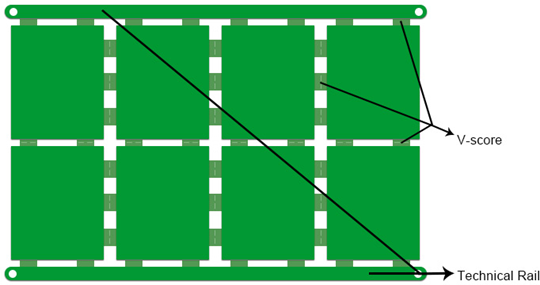
Although technical rail isn't a real element making up printed circuit boards (PCBs), it plays a role of much significance for PCBs going through Surface Mount Technology (SMT) Assembly. As its name indicates, technical rail functions as a rail does. A conveyor belt is applied in SMT assembly process to transfer PCBs to go through solder paste printing, pick and place, reflow/wave soldering and inspection. Circuit boards will never be able to be safely and efficiently transferred unless they are accurately stuck to conveyor belt through technical rail. Figure 1 below demonstrates a structure of technical rail.

Why is Technical Rail Needed?
The major responsibility of technical rail lies in its role as manufacturing "assistant", namely to make manufacturability of assembly go smooth. It stems from the demand that SMT mounter rail requires to fix circuit board sides firmly and transfer board into reflow soldering oven. Therefore, if components are designed too close to the edge of board, components will possibly suffer from "attack" when being picked and placed or soldered, leading to errors or even failures. Apart from SMT assembly, this circumstance also applies to thru-hole components assembly and wave soldering.
What PCBs Call for Technical Rail?
In spite of the significance of technical rail to PCB assembly, not all PCBs have to depend on technical rail in assembly procedure. After all, technical rail generation leads to increased overall cost. Then what type of PCBs call for technical rail?
Generally speaking, two elements play a leading role in determining whether technical rail is needed or not. Once either element is met, technical rail has to be taken into serious consideration:
1. Distance between components placement and board edge. If the distance between component and board edge is designed to be less than 3mm, components are so close to PCB edge that errors or failures are likely to happen. Technical rail is required to widen the distance between components positions and the conveyor belt of mounting device.
2. Fiducial marks. When fiducial marks are not available on PCBs, technical rail is called for WHERE fiducial marks should be accurately planted so that correct coordinates can be ensured to make component positions totally conforming to the requirement regulated in design files.
What Should be Considered on Technical Rail?
1. Width of Technical Rail. Generally speaking, the width of technical rail is in the range from 1.5mm to 5mm based on specific assembly requirement and assembly device parameter requirement. Therefore, it's of much necessity to enquire contract assembler to ensure that your design is compatible with corresponding assembly equipment.
2. Cost of Technical Rail. With technical rail manufactured, material consumption will definitely be increased, and so will the overall cost. How to balance PCB cost and manufacturability can be regarded as the first consideration taken by both PCB design engineers and PCB fabricator or assembler. To minimize cost, the usual method lies in minimum application of technical rail by designing optimal arrangement for PCB panels, which is capable of shrinking the application of technical rail to the largest extent. A reliable PCB fabricator or assembler has sufficient knowledge and experience to provide an ideal scheme for customers based on quality and cost consideration.
How to Remove Technical Rail?
Since technical rail doesn't belong to the mechanical system of circuit boards, it won't be useful any more after the PCB fabrication or assembly, and you should consider to remove it from those boards. Currently, there are three methods to remove technical rail:
1. Router depaneling machine. It is the most effective option when comes to quality alone. This machine mainly depends on milling cutter that can separate panel PCBAs into independent pieces with high-speed rotation according to programmed route. Compared with V-cut depaneling machine, it features an obvious advantage that V-cut depaneling machine can only cut panels along straight lines whereas it goes far beyond that. Furthermore, it leads to clean and neat board edge while V-cut depaneling machine or manual depaneling usually tend to cause blur. Therefore, it contributes to quality improvement and scrap reduction but is highly expensive with complicated operation program and low flexibility.
2. V-cut depaneling machine. It implements cutting operation along v-grooves in straight lines with relatively high cost of blade consumable. The overall cost, however, is lower than that of Router depaneling machine.
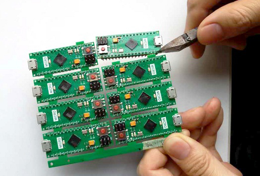
3. Manual depaneling. It relies on hand or needle nose pliers for separation with advantages of convenient operation and low cost. Nevertheless, larger mechanical stress may be generated so that components near board edge will possibly suffer from breakdown.

The following table shows a detailed comparison between those methods discussed above.
Method | Advantage | Disadvantage |
V-cut Depaneling Machine |
|
|
Router Depaneling Machine |
|
|
Manual Depaneling Machine |
|
|
Capacités
Capacité PCB rigide
Capacité PCB flexible
Capacité d'assemblage PCB
Équipement PCB
Équipement d'assemblage PCB
Méthodes de paiement
Prix spéciaux
Transporteurs
Support pour amateurs
Certificat
Assistance clientèle
Suivez-nous
Tel: 1-905-339-2881
Email: sales@goldphoenixpcb.com , tech@goldphoenixpcb.com
Copyright Gold Phoenix PCB Co., Ltd. 2011 - 2026
Tel: 1-905-339-2881 Email: sales@goldphoenixpcb.com , tech@goldphoenixpcb.com
Système de contrôle qualité | Service produit
| Liens
Copyright Gold Phoenix PCB Co., Ltd. 2011 - 2026


