I.DESIGN THE RIGHT SHAPE

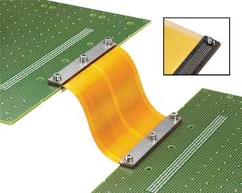
Figure 1Flex board works as a connector
According to the orders Gold Phoenix received, most of the times the flex board works a cable connector to connect two rigid circuit board, Figure 1shows an example. Prototyping flex board is more expensive than rigid board (goldphoenox’s min order for flex board is listed on https://www.goldphoenixpcb.com/pcb-special-price.html), so it is a good ideal to make sure the shape and length you design in your CAD program is right. What you can do is to us a scissors to cut a paper or plastic to make sure the design is right.

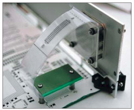
Figure 2Use plastic to simulate the flex board shape
Figure 2is an example illustrates this point perfectly. The engineer plotted the flex outline on clear plastic, cut up some old PCBs and rigid plastic and created a beautiful model of the circuit assembly. He discovered that while the shape looked perfect in his CAD model, there was not enough slack for inserting and removing the connectors. Worse yet, if there were any misalignment of the panel to the PCB, the flex circuit would be severely torqued and very likely tear. He then changed the path of the flex and added three inches of length, and now the flex fits better and the connectors can be installed and removed reliably.
Section
I.DESIGN THE RIGHT SHAPE
II.DESIGN THE RIGHT PAD PATTERN
Please login and click here to download the PDF file: Download


