Knowledge Center
This Gold Phoenix PCB Knowledge Center article reviews the key factors for choosing laminate material for rigid PCBs.
For all PCBs, the main component is the base laminate material. Choosing what you want to use is not simple. There are many options and many flavors that can be used, but how do you know what to pick and how do you note it as the material of choice on the fabrication package?
This article reviews some of the factors to consider when choosing the right laminate material for your PCB.
First, consider all rigid PCBs in general — all types, and the option of FR4 or other materials. In all cases, it is best to refer to IPC standards, IPC-4101 and IPC-4103, using the slash (/) number as assigned by IPC. This slash number is an identifier for the criteria that must be met for structural properties and testing results of the printed circuit board. The slash number can be cross-referenced by your PCB supplier to be sure the materials are in stock and meet or exceed the properties.
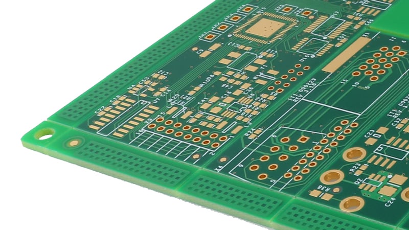
Printed circuit board manufactured with FR4 laminate material.
There are many laminate manufacturers out there that are constantly developing new materials for the production of raw circuit boards. Knowing what criteria are needed for your product and providing the IPC slash number to your supplier allows for options, such as using stock that is on hand, avoiding costly MOQs to purchase specific materials, keeping lead time to a minimum, and purchasing commonly used material with greater availability.
Searching for data sheets is one way to find what you are looking for when it comes to materials; however, consulting with your PCB manufacturing facility is also a great option. Most will have a list of what their common stock is and should be able to guide you to an appropriate material.
There are several PCB characteristics or attributes to consider when selecting laminate material for fabrication. Since all printed circuit boards are unique and built-to-print, often the choice is not black or white. So, how do you decide? Consider items like impedance factors — the sum of the resistance and the reactance, simply the flow of the electronic signal from point to point and how it reacts or responds — microwave printed circuit boards, and commonly used specialty high-speed materials to meet required values.
If the part requires special materials, this should be a clear note on the print to include the expectations for impedance layers and Ohms to be met.
For high-speed PCB circuits requiring tighter controls for impedance routing, the Dk should be considered. Consult your supplier of high-technology printed circuit boards for the best value and easily accessible laminate to meet your proposed stack-up. There are newer materials that have been introduced to manufacturing that are as good as the most commonly used brands.
Providing a specific stack-up with copper weight values, impedance requirements, and thicknesses to your supplier will allow engineering to evaluate stock against your callout. The sooner you involve your PCB supplier, the better.
With all the fancy changes in the industry regarding high tech, blind and buried microvias, high layer count, and such, there is still plenty to consider on the lower tech side. Many parts are still seen at the quote stage that are through hole technology with 1 side surface mount devices on the top. There are still factors to consider for lower technology boards and the appropriate material.
What laminate should you use in this instance? While it is common for customers to be concerned with cost savings on the PCB, it is not as easy to cut costs as one would think. Everyone wants the best price but to also still have great quality product and delivery. Saving on the cost of printed circuit boards and skimping on the base laminate isn’t a good idea. Your base laminate should meet the criteria of the end product assembled.
If you have SMDs and are using lead-free surface finish and lead-free components for processing, you may go with 170tg for your laminate.
The assembly process for lead-free is much hotter for the lead-free component assembly than it is for leaded or HASL parts. There is a chance of an issue of delamination with a standard FR4. Multiple assembly cycles are sometimes needed to complete the full assembly. Add in rework cycles, hand soldering assembly that has sketchy temperatures, and a high-temperature material is best to withstand the processing. If you are getting the lead out, it is recommended to always go with a higher temperature material. There are many options for lead-free surface finish treatment that can be applied.
During the development stages of your PCB, consult with manufacturing on the most up-to-date materials and what you need for the laminate to meet for dielectric thickness, Dk, Tg. Knowing what is in stock and readily available is advantageous and can be a cost-saver. Sticking with more commonly used laminate material stock makes for an easy transition from prototype to production level, as well as when revising the part.
Capabilities
Payment Methods


Specials Price
Carriers


Support Hobbyist
Certificate


Customer Support
Follow Us