Knowledge Center
This Gold Phoenix PCB Knowledge Center article explains the surface mount assembly procedure of Package on Package (PoP) components.
Package on package (PoP) is an integrated circuit packaging method to combine vertically discrete logic and memory ball grid array (BGA) packages. Two or more packages are installed atop each other, i.e. stacked, with a standard interface to route signals between them.
The PoP technology occurs to cater to electronics industry’s constantly demands of fine pitch, smaller size, high signal processing speed and smaller mounting real estate towards electronic products such as smart phones and digital cameras. When applying this technology in the PCB assembly process, electric connection occurs between memory devices at upper package and logic devices at lower package, those devices can even be tested and replaced alone. All of these features help reduce PCB assembly costs and complexity.
There are two widely used PoP structures, namely Standard PoP Structure and TMV PoP Structure.
In a standard PoP, logic devices are placed at the bottom package and logic devices feature a structure of fine pitch BGA solder in harmony with device’s attribute of a large number of pin counts. The top package in the structure of a standard PoP contains memory devices or stacked memories. Owing to insufficient pin counts memory devices contain, margin array can be applied so that interconnections between memory devices and logic devices at the margin of two packages.
Currently wire bonds are fast being replaced by flip chip technology in bottom package to meet higher demands of smaller package size, which cause solder pitch in bottom package constantly going down. 0.4mm solder pitch has been commonly applied in bottom package. Moreover, both dynamic random-access memory (DRAM) chip and DRAM chip containing flash memory in upper package strive for higher speed and bandwidth. Correspondingly, top package should have more solders, which make it necessary to reduce solder pitch of upper package. Initially, a pitch of 0.65mm was far sufficient while finer pitch is currently required. Just like what was mentioned just now, a pitch of 0.4mm has been widely applied in PoP structure.
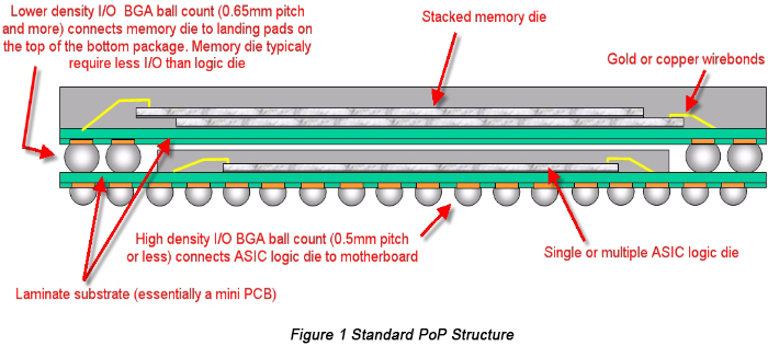
Miniaturization through high integration is the key element contributing to wide popularity of PoP. Leading elements determining PoP size include:
Maximum size of a bare logic device
I/O interface counts for logic devices
Overall bus count of power and ground
Dimensions of memory devices in upper package that provide overall I/O, power, ground and mechanical support
High-density wiring and cross network required by configuration of logic and memory devices integrated in BGA
The overall solder count demanded by bottom package and concerning area
Through mold vias (TMV) PoP, a creation and improvement based on standard PoP, has been widely applied in handheld electronic applications owing to its merit of fine pitch. Figure 2 displays the structure of TMV PoP.
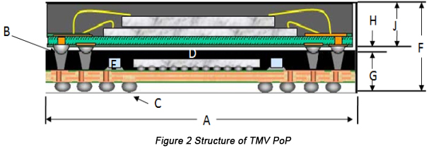
The following table indicates the leading dimensions of a structure of TMV PoP.
| Parameter | Specification |
|---|---|
| Package (A) | 14×14mm |
| Upper solder array (B) | Pitch: 0.5mm · Pads: 200 · Array: 27×2 |
| Bottom solder array (C) | Pitch: 0.4mm · Pads: 620 · Array: 33×6 |
| Silicon wafer (D) | 7.10mm × 6.97mm × 0.13mm |
| Passive component (E) | Size: 0105 · Quantity: 32 |
| Stacked package (F) | Through mold top: 0.40 · Under layer: 0.21mm · Bottom package height: 0.76mm · Clearance (H): 0.03mm · Top package height (J): 0.53mm · Overall height: 1.32mm |
In a TMV PoP, through mold vias are responsible for electric connection between logic device in top package and memory device in bottom package which is achieved by through mold vias in bottom package and between top solder in bottom package and solder in top package. Both solders in top package and bottom package were spherical solder prior to soldering after which they became cylindrical objects B points to like those in Figure 2.
TMV PoP is expected to be capable of shrinking package size, thickness and warpage. Moreover, it allows the next generation of PoP to achieve higher interconnection density, performance and reliability. Its advantages include:
Broke bottleneck between pitch and package clearance, help meet demands of increasing memory interface density
Balanced fully-molded structure is beneficial to warpage control so as to meet the demand of reducing bottom package thickness
Dimension ratio is added between chip and package
Contributive to configuration of wire bonding, FC, stacked chip and passive component
Help increase reliability of top components and bottom through mold vias are capable of holding solders with larger volume, supporting larger stand-off height and improving stress distribution of thermal cycling
When it comes to surface mount technology (SMT) modes of PoP, two types of technologies are available: pre-stacked PoP and on-board stacking PoP.
In pre-stacked PoP technique, manufacturers will stack top package and bottom package, carry out soldering to make the combination be a component that is called pre-stacked device, then attach the combined component to printed circuit board (PCB) surface and implement reflow soldering.
In on-board stacking PoP technique, manufacturers will sequently stack bottom package and top package on circuit board. First, they will mount bottom package on circuit board, then mount top package on bottom package after dipping into flux or solder paste. Next, conduct a reflow soldering on the stacking package.
Take a double-side SMT assembly as an example, steps of on-board stacking PoP assembly include:
Non-PoP side component assembly (printing, mounting, reflow soldering and inspection)
Solder paste printing on PoP side
Bottom package and other devices mounting
Top package devices dipping flux or solder paste
Top package mounting
Reflow soldering
Inspection (X-ray or AOI)
Compared with pre-stacked PoP SMT assembly technique, on-board stacking PoP contains two more steps: top package’s flux or solder paste dipping and top component mounting.
Section
Surface Mount Assembly Procedure of PoP Components_1
Surface Mount Assembly Procedure of PoP Components_2
Capabilities
Payment Methods


Specials Price
Carriers


Support Hobbyist
Certificate


Customer Support
Follow Us