HOW TO SPECIFY STIFFENER REQUIREMENTS IN FLEX PCB DESIGN DRAWINGS
Stiffeners are a key design element in most flex designs and have a significant impact on both the performance and reliability of the finished flex circuits. As a result, stiffeners need to be fully and accurately defined in the data set. Not doing so may result in a finished part that does not meet your requirements.
Stiffeners serve the following purposes in a flex design, each of which have unique material and design requirements:
◆ Component/Connector Area Support
◆ Thickness Modification to Meet ZIF Connector Specifications
■ Mechanical Bend Constraints
■ Heat Dissipation
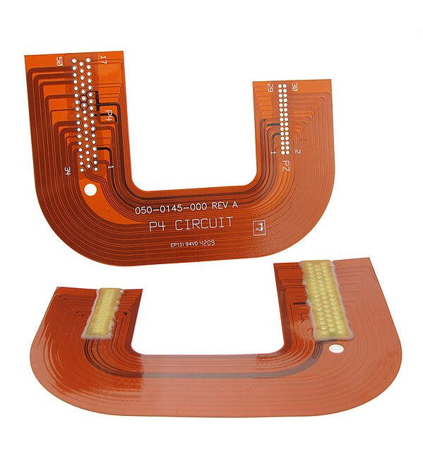
Flex Circuit with Connector Area Support Stiffeners
The two most common stiffener materials used are FR4 and Polyimide.
FR4 Stiffeners
FR4 stiffeners are used to provide support to areas of a flex design that have components and or connectors attached.
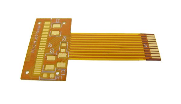
Flex Circuit with FR4 Stiffener
This prevents the flex circuit from being bent at or adjacent to the components/connectors. Doing so would most likely cause the solder joints to be cracked or compromised. FR4 stiffener thickness can range from 0.010” to 0.059” thick with 0.020”, 0.031” and 0.039” being very common.
Polyimide Stiffeners
Polyimide stiffeners are most commonly used in designs that connect to a ZIF (Zero Insertion Force) connector. Connector specifications define that the flex circuit, at the exposed ZIF contact fingers, must be of a specific thickness to engage the connector reliably. The two most common ZIF finger thicknesses are 0.3mm and 0.2mm. Rather than unnecessarily increase the thickness of the entire flex to meet the ZIF specs, a polyimide stiffener is attached locally at the finger areas. Increasing the entire flex thickness would be costly and significantly impact the bend capabilities and mechanical bend reliability of the parts. ZIF specifications also define a very tight tolerance for both the width of the outline and the positional accuracy of the fingers. Polyimide is the only stiffener material that allows the part outline and the stiffener to be profiled and meet all the required connector specified tolerances.
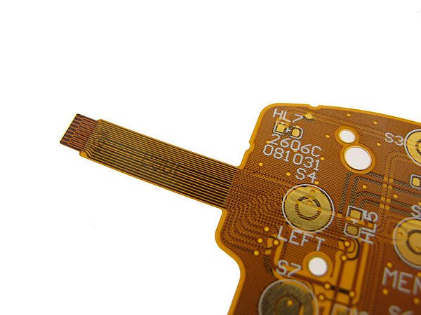
Flex Circuit with Polyimide Stiffener
Polyimide can also be used to support component/connectors areas WHERE there is a restriction in the total part thickness below the 0.010” practical limit of FR4. While polyimide does not provide the same degree of support as FR4 having “a” stiffener is often preferred over “no” stiffener.
Aluminum And Stainless Steel
Aluminum and stainless steel is also used in some designs but come at a significant cost premium over FR4 and Polyimide. Aluminum is commonly used for applications that require heat dissipation. Stainless steel is commonly used when there is very limited space for stiffeners, but the design requires more component area support than what an equivalent thickness FR4 stiffener can provide.
Attaching Your Stiffeners
Stiffeners are attached using either a thermally bonding adhesive which is laminated under heat and pressure, or with a PSA (double sided tape) and placed by hand. The preferred method is thermal bonding adhesive, but design limitations may require use of a PSA. Thermal adhesives are the same flexible epoxy or acrylic adhesives used to attach coverlays to the flex circuit and result in a permanent bond. They are also in most cases more cost effective than PSAs.
For designs with heat dissipation requirements thermally conductive PSAs must be used. Note that these PSAs are not rated to withstand assembly reflow temperatures and require the stiffeners to be attached after component assembly.
Additional Design Requirements
There are also additional design requirements that pertain to stiffeners.
As previously mentioned, ZIF area stiffeners must result in a specific thickness as measured across the ZIF contact fingers and a tight profile width tolerance to ensure accurate engagement with the connector. There is also a minimum stiffener length defined.
ZIF Connector Specifications Example:
FR4 stiffeners, when used in designs with Plated Through Hole (PTH) components and connectors, have the following additional requirements over SMT only designs.
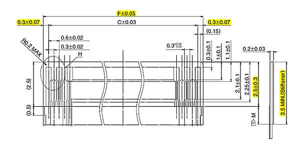
Recommended Flex PCB Dimensions
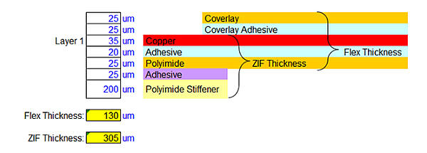
Recommended ZIF Connector Stackup
Attachment side must be on the side of circuit from which the PTH components are inserted from. This allows full access to the component pins and circuit solder pads for soldering purposes.
Clearance holes are necessary to allow PTH pins to pass through the stiffener. Due to manufacturing and material tolerances, the clearances holes must be oversized in relation to the PTH holes in the flex circuit, by 0.016”. This prevents any overlap between stiffener clearance holes and the plated flex holes due to accumulation of tolerances.
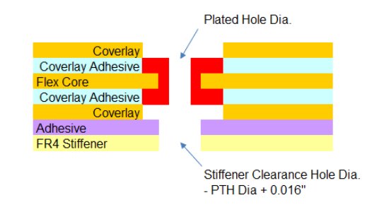
FR4 Stiffeners with Plated Through Hole Design
Clearance holes for non-plated tooling holes are also typically oversized by 0.016” in relation to the required hole size in the flex circuit. If the design requires the same size non-plated hole in the circuit and the stiffener, then this can only be is manufactured using a secondary drilling operation. Please note that this process requires a higher hole location tolerance, +/- 0.005”, due to manufacturing tolerances.
Accurate Data Sets
To fully and accurately define the stiffeners, data sets require the following information:
Stiffener Dimensions/Outline:
◆ Supplied as an Additional Mechanical Gerber File(S) (Preferred) or as a 1:1 DXF File(S)
◆ Defined in Mechanical Drawing
◆ One for Each Stiffener
Stiffener Material Type:
◆ Call Outs in Both the Drawing Notes and The Material Stack Up
◆ Example in image below
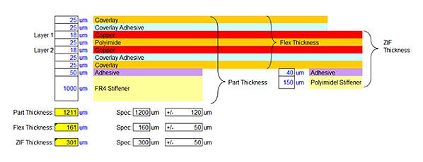
Stiffener Callout in Material Stack-Up
Attachment Method:
◆ Defined in Both the Drawing Notes and The Material Stack Up
Stiffener Attachment Side(s):
◆ Defined in Material Stack Up
Stiffener Drill File and Hole Sizes (If Required for PTH Designs):
◆ Supplied as Additional Drill File(s) With Drill Chart(s)
ZIF Connector(s) Manufacturer(s) and Part Number(s):
◆ Defined in Mechanical Drawing and Drawing Notes
◆ Reference to Specific Location with Designs with More Than One ZIF Connector
Summary
Stiffeners are an important element in most flex designs and as such need to be engineered into the design and fully documented in the data set to ensure the form fit and function of the finished flex circuit parts. Some designs may have complex stiffener requirements that may impact the manufacturability of the flex circuits and may create added complexity in the component assembly process. For these designs we recommend that our customers consult with an engineering team to ensure the flex circuit both manufacturable and will meet your requirements.
Capabilities
Payment Methods
Specials Price
Carriers
Support Hobbyist
Certificate
Customer Support
Follow Us
Tel: 1-905-339-2881
Email: sales@goldphoenixpcb.com , tech@goldphoenixpcb.com
Copyright Gold Phoenix PCB Co., Ltd. 2011 - 2026
Tel: 1-905-339-2881 Email: sales@goldphoenixpcb.com , tech@goldphoenixpcb.com
Quality Control System
|
Products/Service
|
Friendly Links
Copyright Gold Phoenix PCB Co., Ltd. 2011 - 2026


